|
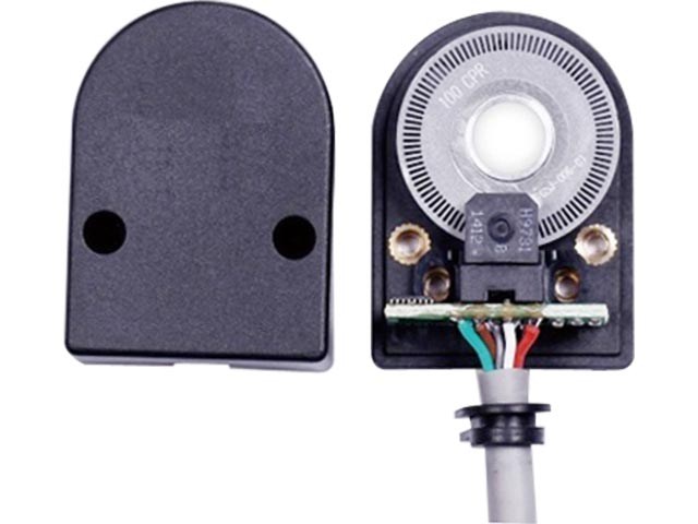
HKT3004 Series 2 ChannelsHollowShaft Incremental Encoder Application Motorized spindle , DC Motor , Servo motor, printers, plotters, tape drives, positioning tables ,and automatic handles.
Motor encoders are used in many applicaions that reauire precise shat unlimited rotaion-incuding industrial controls. robotics. speciapurpose photographic lenses,computer input devices (such as optomechanical mice and trackballs), controlled stress rheometers, and
rotating radar platforms.
Features 2 Channels quadratureoutput , quick and easy assembly Cost-effective , ideal for small motor system Resolutions up to 1024counts per revolution, TTL compatible
A motor encoder, is an electro-mechanical device that converis the angular position or motion of a shaf or axleto an analog or digital code.
There are two main types: absolute and incremental (relative). The output of absolute encoders indicates the curent position of the shaftmaking them angle transducers. The output of incremental encoders provides information about the motion of the shaf, which is typically further processed elsewhere into information such as speed, distance and position.
|
Ordering Information

Note
1, Please contact sales representative to confirm the correctness and availability of the part number
2, Line Drive is only available with 5V DC option
3, 1000/1024 PPR is only available with mylar disk
Technical Specifications
|
Electrical Specification |
||||
|
Output circuit |
Line driver output/ Voltage output |
|||
|
Power Vcc |
5VDC |
|||
|
Current Consumption |
≤65mA |
|||
|
High-level output |
Min Vcc*85% |
|||
|
Low-level output |
Max 0.3V |
|||
|
Rise Time Tr |
Max 200ns |
|||
|
Fall Time Tr |
Max 50ns |
|||
|
Max Responding Frequency |
100kHz |
|||
|
Mechanical Specification |
||||
|
Max speed(r/min) |
Starting Torque |
Max. Shaft Loading |
Shocking |
Vibration |
|
12000 |
<0.05Nm |
Radial:25N, Axial:15N |
50G/11ms |
10G 10-2000Hz |
|
Rotor Inertia |
Working Temperature |
Storage Temperature |
Protection Grade |
Weight |
|
4*10-8Kgm2 |
-20~85℃ |
-20~85℃ |
IP50 |
100g |
Output Phase Shift
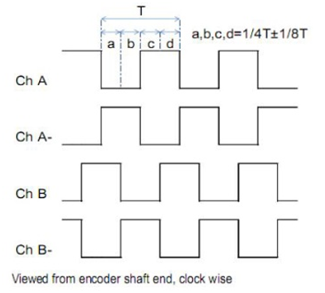 |
Wave Ratio: a+b=0.5T±0.1T
c+d=0.5T±0.1T
Z signal Width: Tz=0.5T
Signal position accuracy :
A,B phase absolute angle deviation ≤0.2T |
Periodic Deviation ≤0.05T
T=360°/N (N is output pulse number of each spin ) |
Connection Table
|
Line driver output |
0V |
Vcc |
A |
Ā |
B(-) |
B |
Voltage output |
0V |
Z |
Vcc |
B |
N.C |
|
Code |
1 |
2 |
3 |
4 |
5 |
6 |
Code |
1 |
2 |
3 |
4 |
5 |
|
Color |
Black |
Red |
Green |
Brown |
Grey |
White |
Color |
Black |
Yellow |
Red |
White |
- |
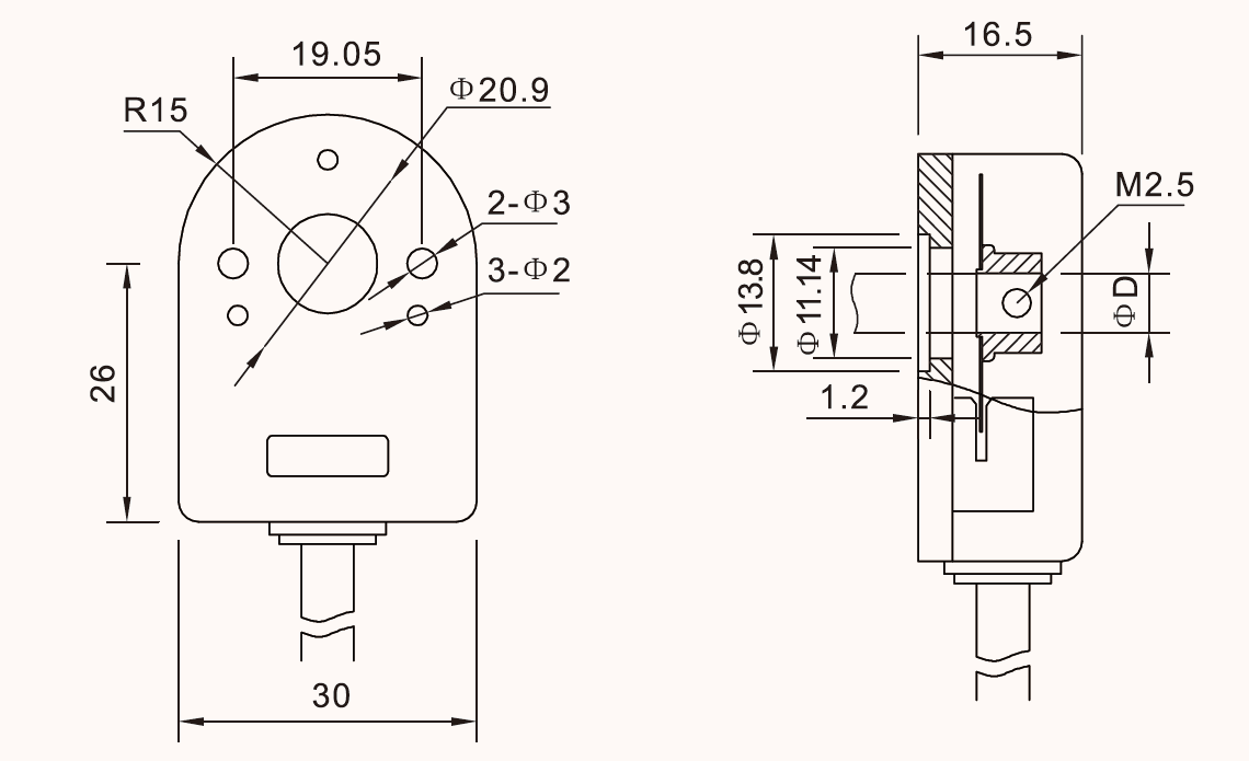
Dimensions(mm)
