|
Application Automated measurement and automatic control system . Measure the angular displacement and placed speed. The measured value could be output with naturel binaries by the encoder.
Absolute encoders are used in many applicaions that reauire precise shat unlimited rotaion-incuding industrial controls. robotics. Specia purpose photographic lenses,computer input devices (such as optomechanical mice and trackballs), controlled stress rheometers, and rotating radar platforms.
Features High strong anti-interference , won’t be affect by power off or system shut off and start Dust proof, and moisture proof, high shock and vibration resistance
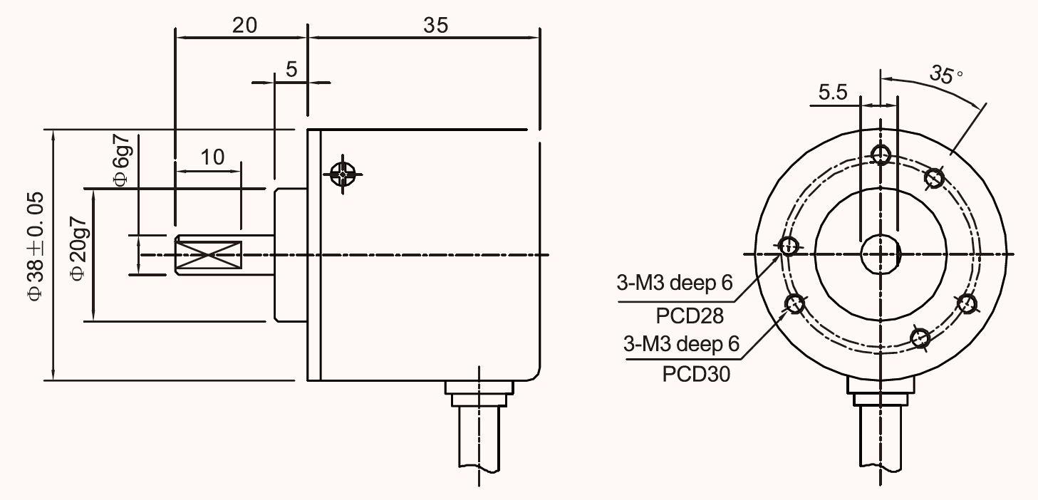
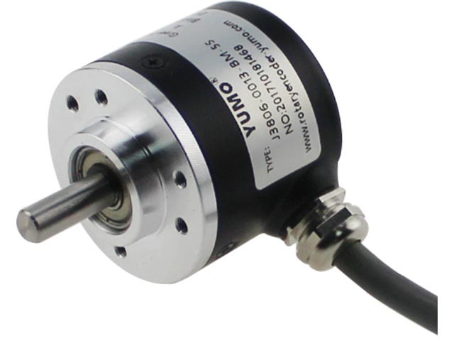
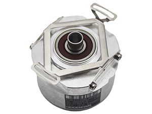
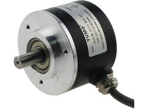
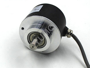
A Solid Shaft Absolute Rotary Encoder, also called a absolute encoder, is an electro-mechanical device that converis the angular position or motion of a shaf or axleto an analog or digital code.
There are two main types: absolute and incremental (relative). The output of absolute encoders indicates the curent position of the shaft making them angle transducers. The output of incremental encoders provides information about the motion of the shaf, which is typically further processed elsewhere into information such as speed, distance and position.
Ordering Information
|
Parameter
|
Code |
Absolute Code |
|||||
|
Bit |
Point for Round |
Angle Resolution |
Output code |
Carry direction |
Accuracy |
|
|
J3806G-0013 |
13 |
8192 |
360/213 |
Natural Binary |
from shaft according to clock wise(CCW) |
±1.5 |
|
J3806G-0012 |
12 |
4096 |
360/212 |
Natural Binary |
from shaft according to clock wise(CCW) |
±3 |
|
J3806G-0011 |
11 |
2048 |
360/211 |
Natural Binary |
from shaft according to clock wise(CCW) |
±6 |
|
J3806G-0010 |
10 |
1024 |
360/210 |
Natural Binary |
from shaft according to clock wise(CCW) |
±12 |
Note
1, Please contact sales representative to confirm the correctness and availability of the part number
Technical Specifications
|
Electrical parameter |
|||||||||||||||
|
Code |
Power |
Output signal |
Consumption current |
Rise/fall time |
Response frequency |
|
|||||||||
|
High level (V) |
Low level (V) |
Allowed current |
|||||||||||||
|
J3806 |
5VDC |
≥2.5 |
≤1 |
mA |
<100mA |
<us |
0-1m |
>1MΩ |
|||||||
|
Mechanical parameter |
|||||||||||||||
|
Revolution |
Starting torque25° |
Load of Axis |
Working temperature |
Storage temperature |
Relative humidity |
Shock Resistance |
Vibration proof |
||||||||
|
Axial |
Radial |
||||||||||||||
|
0-6000r/min |
2*10-3N/m |
10N |
20N |
-25~100℃ |
-30~110℃ |
30-85% |
30m2/s(10-200Hz, x,y,z) |
30m2/s(11ms, x,y,z) |
|||||||
Connection Table
|
Color |
Red |
Black |
Green |
White |
Yellow |
Brown |
Grey |
Orange |
Shielded |
|
Voltage E |
Vcc |
0V |
Clock |
Date |
Backup |
- |
- |
Backup |
Shell |
|
Line driver TTL |
Vcc |
0V |
Clock |
Date |
Backup |
- |
|
Backup |
Shell |
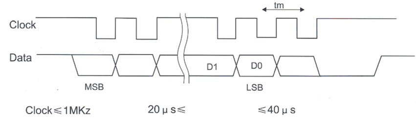
SSI signal interface
|
|
|
