Analysis of Encoder Chip Scheme for Industrial Control
Encoder is a sensor that encodes the rotation angle and linear displacement, and is widely used in the field of industrial control when paired with motors. The encoder that detects rotation is called a rotary encoder, and the encoder that detects linear displacement is called a linear encoder. In order to quickly and accurately control industrial robots, it is necessary to detect their motion status in real-time, including rotation angle, movement distance, and rotation/movement speed. The rotary encoder plays an important role.
Encoders are the core components of industrial robot control.
Encoder is a sensor that detects rotation angle, linear displacement, and speed. So what is the mechanism for detecting rotation and angle using a rotary encoder?
The process of converting rotational motion into rotational information.
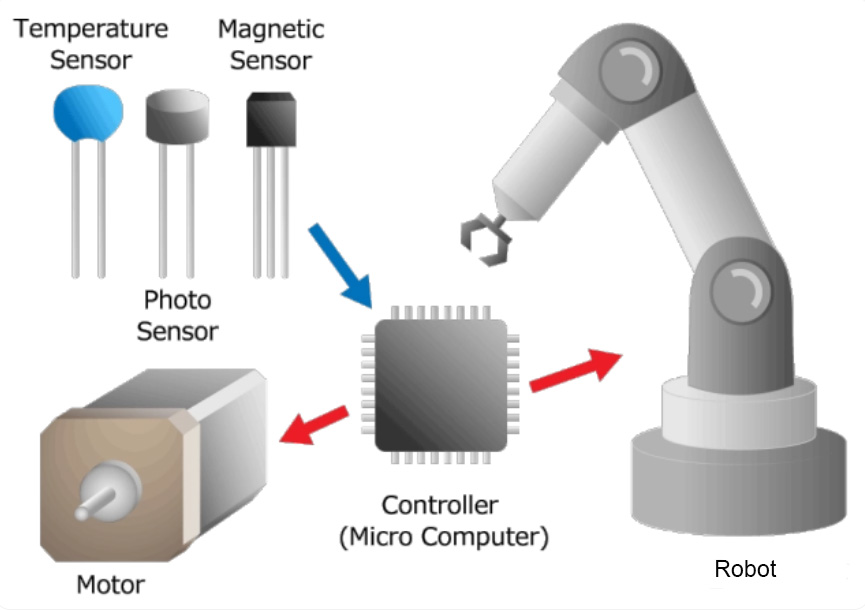
The core component of an encoder is a sensor, which is a component or electronic component that detects changes in natural phenomena. For example, optical sensors detect the on/off of light, while magnetic sensors detect the distribution of magnetic fields. Sensors have the following functions: by outputting detected physical quantity changes as electrical signals, and can send information to the outside world. As shown in the above figure, the encoder outputs electrical signals from sensor components, and finally sends rotation/angle information as digital or analog electrical signals to the outside.
What types of rotation and angle information are available?
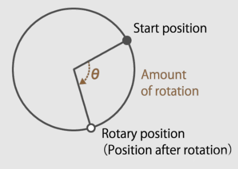
What is the rotational state? Taking the motor as an example, it stops running, rotates clockwise, counterclockwise, rotates at a constant speed, accelerates, decelerates, and so on. Accurately mastering these conditions and accurately controlling the motor requires four types of information: rotation amount, rotation speed, rotation direction, and rotation position.
1. Rotation angle
Rotation Description
This is information about how many times the motor shaft angle has moved. For example, in a brushless DC motor, the rotation of the rotor can be determined by detecting changes in the magnetic poles of the rotor, effectively causing the motor to rotate.
2. Speed: This is information about the rotational speed of the motor shaft. As mentioned earlier, servo motors detect the speed of brushless DC or AC motors and perform feedback control to rotate the motor shaft at the speed set by the servo amplifier.
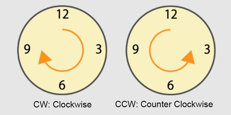
3. Rotation direction: This is information about the direction of rotation (clockwise or counterclockwise) of the motor shaft. In a system that detects the rotation of the motor shaft through the number of pulses output from the encoder, if the rotation direction cannot be recognized, the rotation amount is erroneously counted.
4. Rotation position: This is information about how many degrees the motor shaft angle is.
As we mentioned earlier, servo motors and stepper servo motors use encoders to detect rotation angles and perform feedback control, while also determining whether the target rotation angle has been reached. Thus achieving high-precision position control.
The difference in the physical quantity to be measured means the difference in the detection method of the sensor, so it is an important component that determines the advantages and disadvantages of the encoder.
According to the detection method, encoders are divided into the following four types: mechanical, optical, magnetic, and electromagnetic induction types:
1. Mechanical (contact) encoder
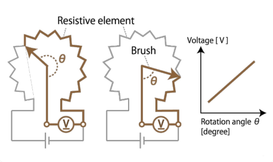
This method uses a variable resistor to detect the rotation position, and the resistance of the variable resistor changes proportionally to the rotation angle. This type of mechanical encoder is commonly referred to as a potentiometer. When the slider moves on the resistance, the resistance value of the potentiometer will change proportionally to the distance the slider moves.
2. Optical encoder
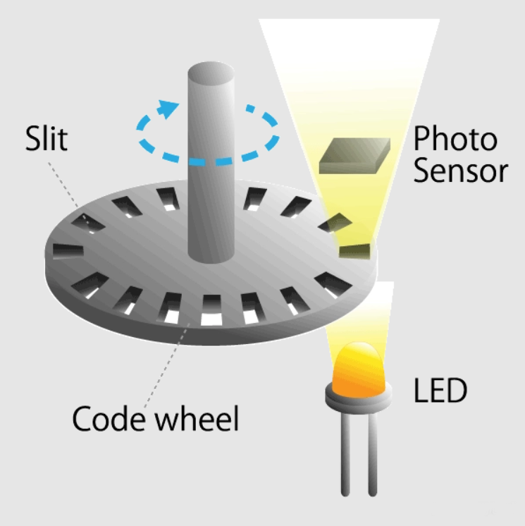
This is a method of using photoelectric sensors to detect whether light passes through the radial gaps of the code disk installed on the motor shaft during rotation. The light pulse signal undergoes changes when passing through a slit, and the rotation of the motor shaft can be detected by counting the number of pulses.
3. Electromagnetic encoder
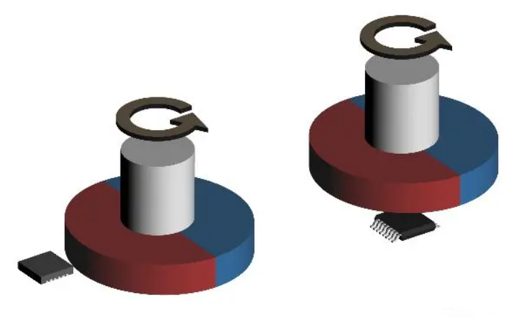
This method uses magnetic sensors to measure the changes in magnetic field distribution generated by permanent magnets installed on the motor shaft. When the motor rotates, the magnetic field distribution of the permanent magnet also changes. Therefore, if a magnetic sensor is used to detect it, the rotation position of the motor shaft can be determined.
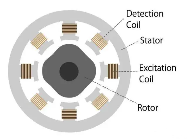
4. Electromagnetic induction encoder
This method reads the magnetic field changes generated between the induction coil (excitation coil) and the fixed coil (detection coil) installed on the motor shaft. The basic principle is the same as using electromagnetic induction transformers, and this type of encoder is called a rotary transformer or capacitive encoder. Due to the contact method of using brushes, there is a risk of wear and tear on the power supply of the rotating induction coil of the rotary transformer. However, there is a VR (variable reactance) parser that can improve this risk.
According to the form of electrical output, encoders can be divided into incremental encoders and absolute encoders. The output of an incremental encoder is a periodic repetitive signal, such as a square wave or sine wave pulse. Therefore, it can be divided into square wave incremental encoders and sine and cosine wave incremental encoders. The square wave incremental encoder is one of the most commonly used encoders, which calculates the length and velocity of square wave pulses by calculating their quantity and frequency. The square wave incremental encoder has voltage output, such as TTL (also known as long line drive, line drive, or RS422) and HTL (also known as push-pull output or push-pull output); There are switch type outputs, such as NPN open collector output and PNP open collector output. The output of sine and cosine wave incremental encoders is generally 1Vpp or 0.5Vpp sine and cosine waves. By calculating the amplitude of sine and cosine waves, small angles can be accurately distinguished. The output of an absolute value encoder represents a specific numerical encoding of the actual position, and different encoding rules correspond to different communication protocols, which are commonly referred to as communication interfaces. The common communication interfaces for absolute value encoders are:
Analog quantities (such as 4-20mA current type output and 0-10V voltage type output);
Parallel ports (such as push-pull output and open collector output, where each wire core represents a binary digit);
Serial ports (such as RS485, RS232, RS422, etc.);
Industrial bus interfaces (such as SSI, PROFIBUS, DeviceNet, CANOpen, etc.);
Industrial Ethernet interfaces, such as PROFINET, Ethernet IP, EtherCAT, POWERLINK, etc.
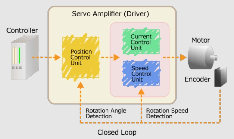
Absolute encoders include single turn absolute encoders and multi turn absolute encoders. A single turn absolute encoder can determine the angle within one turn range, while a multi turn absolute encoder can determine the number of turns in addition to determining the angle within one turn range. According to usage, encoders can be roughly divided into commercial grade and chip grade, economy grade, standard industrial grade, and various special industrial grade. For example, the encoder inside a printer or magnetic card machine has a simple structure and many casings are not available. There is almost no need to talk about temperature, dust, waterproof, and electromagnetic compatibility, and the price is extremely cheap. Chip level: The price is very low, currently provided by some semiconductor chip manufacturers abroad or simply packaged by downstream manufacturers. There is no shell or a simple shell, and the power and signal are only for simple processing, suitable for the development of secondary circuits by manufacturers. The distance between the receiving line and the encoder should not exceed 50cm. Some flow meters and valve electrical adjustment manufacturers choose this level. The protection and electromagnetic compatibility anti-interference of this type of encoder should be taken into account by the manufacturer of secondary development, If not understood, it is more likely to cause damage. Economy level equipment already has simple packaging and simple processing, which is suitable for single machine equipment, such as embroidery machines. However, the characteristic of economy level equipment is its cost-effectiveness compared to industrial level equipment. Its design and material selection are positioned in an economical manner and are not suitable for large equipment, assembly lines, and engineering projects. Industrial level design, material selection, and testing are all done according to standard industrial requirements, and as important components of industrial control systems, they are applied to various industrial equipment Robots, assembly lines, and engineering projects. A servo mechanism is a mechanism that maintains a constant speed for continuous or linear motion, or precisely controls the rotation angle and movement distance of a motion. The servo mechanism consists of a brushless DC or AC motor, an encoder, and a driver. In order to maintain a constant speed for brushless DC or AC motors, the encoder detects the speed.
If the detected speed is slower than the set rotation speed, the servo amplifier controls the motor to rotate faster;
If the detected speed is less than the set rotation speed, the servo amplifier controls it.
In order to accurately control the rotation angle of the motor, the encoder detects the rotation angle. The servo amplifier controls the rotation angle of the motor by checking whether it has moved to the target rotation angle. This control method of using an encoder to detect motor speed and rotation angle is called feedback control (closed-loop).
To summarize, an encoder is a type of sensor that utilizes sensing principles such as optoelectronics, electromagnetism, capacitance, or inductance to detect the speed, position, angle, distance, or count of mechanical motion.